接着上一篇继续实验哈!
路由协议配置实验
3.1 实验目的:
1.熟悉主机的路由配置;
2.熟悉路由器的路由配置;
3.掌握RIP协议的基本配置;
4.掌握IGRP协议的基本配置;
5.区别以上两种路由协议的特点。
3.2 实验环境
实际组网中路由器是用来连接两个物理网络的,为了模拟实际环境,我们在实验中采用背靠背直接相连来模拟广域网连接。由于时间限制,让我们先完成几个简单的背靠背实验,每个对应一个相对独立的内容。如果时间充足,可以完成后面的综合性实验,进一步提高动手能力,深层理解路由协议。下面是简单实验的模拟实验环境,共两台路由器,一台交换机,两台PC。
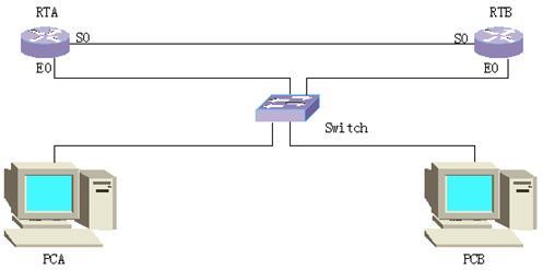
按照上图的实验组网建立实验环境。为了不受路由器原来的配置影响,在实验之前请先将所有路由器的配置数据擦除后重新启动。交换机在此只用作连接主机和路由器用,以便全采用标准网线连接,不需配置。
3.3实验步骤:
3.3.1静态路由
清空路由器的原有配置
Quidway>enable
Quidway#erase
Quidway#reboot
重新启动路由器后,查看初始配置并显示路由表如下:
Quidway#show running-config
Now create configuration...
Current configuration
!
version 1.5.6
!
interface Aux0
async mode interactive
encapsulation ppp
!
interface Ethernet0
speed auto
duplex auto
no loopback
!
interface Serial0
encapsulation ppp
!
interface Serial1
encapsulation ppp
!
end
Quidway#show ip route
Routing Tables:
Destination/Mask Proto Pref Metric Nexthop Interface
127.0.0.0/8 Direct 0 0 127.0.0.1 LoopBack0
127.0.0.1/32 Direct 0 0 127.0.0.1 LoopBack0
配置路由器接口和PC的IP地址
路由器各接口的IP地址如下:
|
|
RTA |
RTB |
|
E0 |
202.0.0.1/24 |
202.0.1.1/24 |
|
S0 |
192.0.0.1/24 |
192.0.0.2/24 |
PC的IP地址和缺省网关Gateway如下:
|
|
PCA |
PCB |
|
IP |
202.0.0.2/24 |
202.0.1.2/24 |
|
Gateway |
202.0.0.1 |
202.0.1.1 |
为了标识路由器,我们修改路由器名称分别为RTA、RTB并按照上述表格完成IP地址的配置之后,再次查看配置信息和路由表信息如下:
RTA#show running-config
Now create configuration...
Current configuration
!
version 1.5.6
hostname RTA
!
interface Aux0
async mode interactive
encapsulation ppp
!
interface Ethernet0
speed auto
duplex auto
no loopback
ip address 202.0.0.1 255.255.255.0
!
interface Serial0
encapsulation ppp
ip address 192.0.0.1 255.255.255.0
!
interface Serial1
encapsulation ppp
!
end
RTA(config-if-Serial0)#show ip route
Routing Tables:
Destination/Mask Proto Pref Metric Nexthop Interface
127.0.0.0/8 Direct 0 0 127.0.0.1 LoopBack0
127.0.0.1/32 Direct 0 0 127.0.0.1 LoopBack0
192.0.0.0/24 Direct 0 0 192.0.0.2 Serial0
192.0.0.1/32 Direct 0 0 127.0.0.1 LoopBack0
192.0.0.2/32 Direct 0 0 192.0.0.2 Serial0
202.0.0.0/24 Direct 0 0 202.0.0.1 Ethernet0
202.0.0.1/32 Direct 0 0 127.0.0.1 LoopBack0
RTB的相关信息类似RTA,可以自己在实验中显示比较。注意:串口的配置需要在接口配置模式下完成shutdown和no shutdown命令之后才生效。完成上述配置之后,用ping命令测试网络互通性,会发现两个以太网段不能互通。你知道为什么吗?仔细看看路由表就可以明白,路由器还没有相关的路由项。在这里我们采用配置静态路由的办法来添加路由。分别在RTA,RTB上配置到对端以太网段的静态路由,RTA的配置信息和路由表信息如下:
RTA(config)#show running-config
Now create configuration...
Current configuration
!
version 1.5.6
hostname RTA
!
interface Aux0
async mode interactive
encapsulation ppp
!
interface Ethernet0
speed auto
duplex auto
no loopback
ip address 202.0.0.1 255.255.255.0
!
interface Serial0
encapsulation ppp
ip address 192.0.0.1 255.255.255.0
!
interface Serial1
encapsulation ppp
!
exit
ip route 202.0.1.0 255.255.255.0 192.0.0.2 preference 60
!
end
RTA(config)#show ip route
Routing Tables:
Destination/Mask Proto Pref Metric Nexthop Interface
127.0.0.0/8 Direct 0 0 127.0.0.1 LoopBack0
127.0.0.1/32 Direct 0 0 127.0.0.1 LoopBack0
192.0.0.0/24 Direct 0 0 192.0.0.2 Serial0
192.0.0.1/32 Direct 0 0 127.0.0.1 LoopBack0
192.0.0.2/32 Direct 0 0 192.0.0.2 Serial0
202.0.0.0/24 Direct 0 0 202.0.0.1 Ethernet0
202.0.0.1/32 Direct 0 0 127.0.0.1 LoopBack0
202.0.1.0/24 Static 60 0 192.0.0.2 Serial0
RTB的相关信息类似RTA。比较前后路由表发现现在新增了一项静态路由,此时再测试网络互通性,可以ping通了吗?
3.3.2 RIP协议
在上面的实验基础上,删除静态路由的配置之后再启动RIP协议,显示配置信息和路由表信息如下:
RTA的配置和路由表:
RTA#show running-config
Now create configuration...
Current configuration
!
version 1.5.6
hostname RTA
!
interface Aux0
async mode interactive
encapsulation ppp
!
interface Ethernet0
speed auto
duplex auto
no loopback
ip address 202.0.0.1 255.255.255.0
!
interface Serial0
encapsulation ppp
ip address 192.0.0.1 255.255.255.0
!
interface Serial1
encapsulation ppp
!
exit
router rip
network all
!
end
RTA#show ip route
Routing Tables:
Destination/Mask Proto Pref Metric Nexthop Interface
127.0.0.0/8 Direct 0 0 127.0.0.1 LoopBack0
127.0.0.1/32 Direct 0 0 127.0.0.1 LoopBack0
192.0.0.0/24 Direct 0 0 192.0.0.2 Serial0
192.0.0.1/32 Direct 0 0 127.0.0.1 LoopBack0
192.0.0.2/32 Direct 0 0 192.0.0.2 Serial0
202.0.0.0/24 Direct 0 0 202.0.0.1 Ethernet0
202.0.0.1/32 Direct 0 0 127.0.0.1 LoopBack0
202.0.1.0/24 RIP 100 1 192.0.0.2 Serial0
RTB的配置和路由表:
RTB#show running-config
Now create configuration...
Current configuration
!
version 1.5.6
hostname RTB
!
interface Aux0
async mode interactive
encapsulation ppp
!
interface Ethernet0
speed auto
duplex auto
no loopback
ip address 202.0.1.1 255.255.255.0
!
interface Serial0
clock-select DTECLK1
encapsulation ppp
ip address 192.0.0.2 255.255.255.0
!
interface Serial1
encapsulation ppp
!
exit
router rip
network all
!
end
RTB#show ip route
Routing Tables:
Destination/Mask Proto Pref Metric Nexthop Interface
127.0.0.0/8 Direct 0 0 127.0.0.1 LoopBack0
127.0.0.1/32 Direct 0 0 127.0.0.1 LoopBack0
192.0.0.0/24 Direct 0 0 192.0.0.1 Serial0
192.0.0.1/32 Direct 0 0 192.0.0.1 Serial0
192.0.0.2/32 Direct 0 0 127.0.0.1 LoopBack0
202.0.0.0/24 RIP 100 1 192.0.0.1 Serial0
202.0.1.0/24 Direct 0 0 202.0.1.1 Ethernet0
202.0.1.1/32 Direct 0 0 127.0.0.1 LoopBack0
测试网络互通性,应该是全网互通的。如果不是,请检查您的配置是否与上面的一致。现在我们可以看看RIP是怎样发现路由的,再特权模式下打开RIP协议调试开关,有如下信息在路由器之间传递,它们完成了路由的交换,并形成新的路由。
RTA#debug ip rip packet //打开RIP协议调试开关;
Rip packet debugging is on
RTA#configure
Enter configuration commands, one per line. End with command exit!
RTA(config)#logging console //使调试信息从console口输出;
RTA(config)#
RIP: send from 192.0.0.1 to 255.255.255.255(Serial0)
Packet:vers 1, cmd Response, length 24
dest 202.0.0.0 ,Metric 1
RIP:receive Response from 192.0.0.2(Serial0)
Packet:vers 1, cmd Response, length 24
dest 202.0.1.0 ,Metric 1
从上面的信息可以看到RIP协议版本为version 1,这是华为路由器的默认版本。可以用ip rip version 2 mcast命令改变协议版本,再查看debug信息如下:
RTA#debug ip rip packet
Rip packet debugging is on
RTA#
RIP:receive Response from 192.0.0.2(Serial0)
Packet:vers 2, cmd Response, length 24
dest 202.0.1.0 mask 255.255.255.0,router 0.0.0.0 ,metric 1
RIP: send from 192.0.0.1 to 224.0.0.9(Serial0)
Packet:vers 2, cmd Response, length 24
dest 202.0.0.0 mask 255.255.255.0,router 0.0.0.0 ,metric 1
然后使用ip rip version 2 bcast命令改变协议报文的发送方式为广播方式,查看debug信息如下:
RTA#debug ip rip packet
Rip packet debugging is on
RTA#
RIP:receive Response from 192.0.0.2(Serial0)
Packet:vers 2, cmd Response, length 24
dest 202.0.1.0 mask 255.255.255.0,router 0.0.0.0 ,metric 1
RIP: send from 192.0.0.1 to 255.255.255.255(Serial0)
Packet:vers 2, cmd Response, length 24
dest 202.0.0.0 mask 255.255.255.0,router 0.0.0.0 ,metric 1
比较以上三种情况的debug信息,能够发现它们的异同吗?广播地址是什么,组播地址又是什么?华为路由器的默认状态启动了水平分割功能,在以上配置基础上,关闭水平分割(RTA(config-if-Serial0)#no ip rip split)再看看debug信息有什么变化吗?
RTA#debug ip rip packet
Rip packet debugging is on
RTA#
RIP:receive Response from 192.0.0.2(Serial0)
Packet:vers 2, cmd Response, length 44
dest 202.0.0.0 mask 255.255.255.0,router 0.0.0.0 ,metric 2
dest 202.0.1.0 mask 255.255.255.0,router 0.0.0.0 ,metric 1
RIP: send from 192.0.0.1 to 255.255.255.255(Serial0)
Packet:vers 2, cmd Response, length 44
dest 202.0.1.0 mask 255.255.255.0,router 0.0.0.0 ,metric 2
dest 202.0.0.0 mask 255.255.255.0,router 0.0.0.0 ,metric 1
我们比较发现关闭水平分割时,交换的路由信息增加了,这就是水平分割的作用。水平分割规定不能将从某一网关送来的路由信息再送回此网关,这就是为什么关闭水平分割时交换的路由信息增加了。
下面我们再来理解验证路由器的自动聚合功能。先修改各路由器的E0口的IP地址如下:
|
|
RTA |
RTB |
|
E0 |
10.0.1.1/24 |
10.0.2.1/24 |
显示路由器配置信息和路由表信息如下:
RTA#show running-config
Now create configuration...
Current configuration
!
version 1.5.6
logging console
hostname RTA
!
interface Aux0
async mode interactive
encapsulation ppp
!
interface Ethernet0
speed auto
duplex auto
no loopback
ip address 10.0.1.1 255.255.255.0
!
interface Serial0
encapsulation ppp
ip address 192.0.0.1 255.255.255.0
ip rip version 2 bcast
!
interface Serial1
encapsulation ppp
!
exit
router rip
network all
!
end
RTA#show ip route
Routing Tables:
Destination/Mask Proto Pref Metric Nexthop Interface
10.0.1.0/24 Direct 0 0 10.0.1.1 Ethernet0
10.0.1.1/32 Direct 0 0 127.0.0.1 LoopBack0
127.0.0.0/8 Direct 0 0 127.0.0.1 LoopBack0
127.0.0.1/32 Direct 0 0 127.0.0.1 LoopBack0
192.0.0.0/24 Direct 0 0 192.0.0.2 Serial0
192.0.0.1/32 Direct 0 0 127.0.0.1 LoopBack0
192.0.0.2/32 Direct 0 0 192.0.0.2 Serial0
然后在协议配置模式下关闭自动聚合功能,显示路由表信息如下:
RTA(config-router-rip)#no auto-summary
RTA(config-router-rip)#show ip route
Routing Tables:
Destination/Mask Proto Pref Metric Nexthop Interface
10.0.1.0/24 Direct 0 0 10.0.1.1 Ethernet0
10.0.1.1/32 Direct 0 0 127.0.0.1 LoopBack0
10.0.2.0/24 RIP 100 1 192.0.0.2 Serial0
127.0.0.0/8 Direct 0 0 127.0.0.1 LoopBack0
127.0.0.1/32 Direct 0 0 127.0.0.1 LoopBack0
192.0.0.0/24 Direct 0 0 192.0.0.2 Serial0
192.0.0.1/32 Direct 0 0 127.0.0.1 LoopBack0
192.0.0.2/32 Direct 0 0 192.0.0.2 Serial0
比较前后两次的路由表信息,会发现关闭自动聚合功能时增加了一条动态路由,知道为什么吗?然后改变协议版本(ip rip version 1)并使之生效,并在关闭和启动自动聚合功能下显示路由表信息会发现都没有动态路由项产生,知道为什么吗?因为version 1不支持可变长子网掩码,而10.0.1.1与10.0.2.1属于A类地址,自然掩码为8位,属于同一网段的地址。
路由表信息如下:
RTA(config-if-Serial0)#sho ip route
Routing Tables:
Destination/Mask Proto Pref Metric Nexthop Interface
10.0.1.0/24 Direct 0 0 10.0.1.1 Ethernet0
10.0.1.1/32 Direct 0 0 127.0.0.1 LoopBack0
127.0.0.0/8 Direct 0 0 127.0.0.1 LoopBack0
127.0.0.1/32 Direct 0 0 127.0.0.1 LoopBack0
192.0.0.0/24 Direct 0 0 192.0.0.2 Serial0
192.0.0.1/32 Direct 0 0 127.0.0.1 LoopBack0
192.0.0.2/32 Direct 0 0 192.0.0.2 Serial0
你还可以在接口配置模式下配置命令ip rip version 2 mcast后,显示路由表信息看看又是什么情况。比较上述几种情况下的路由信息,总结version 1和version 2的异同,mcast和bcast的异同以及水平分割和自动聚合的功能。
3.3.3 IGRP协议
IGRP协议是RIP协议的改进型距离矢量路由协议,但它有更加准确的综合路有权,适用于更大的网络。下面我们就来研究一下IGRP协议,实验环境同上,将路由器和PC的配置恢复到做RIP协议实验之前的配置。然后启动IGRP协议,显示路由器的配置信息和路由表信息如下:
RTA的相关信息:
RTA#show running-config
Now create configuration...
Current configuration
!
version 1.5.6
logging console
hostname RTA
!
interface Aux0
async mode interactive
encapsulation ppp
!
interface Ethernet0
speed auto
duplex auto
no loopback
ip address 202.0.0.1 255.255.255.0
!
interface Serial0
encapsulation ppp
ip address 192.0.0.1 255.255.255.0
!
interface Serial1
encapsulation ppp
!
exit
router igrp
asystem 100
network all
!
end
RTA#show ip route
Routing Tables:
Destination/Mask Proto Pref Metric Nexthop Interface
127.0.0.0/8 Direct 0 0 127.0.0.1 LoopBack0
127.0.0.1/32 Direct 0 0 127.0.0.1 LoopBack0
192.0.0.0/24 Direct 0 0 192.0.0.2 Serial0
192.0.0.1/32 Direct 0 0 127.0.0.1 LoopBack0
192.0.0.2/32 Direct 0 0 192.0.0.2 Serial0
202.0.0.0/24 Direct 0 0 202.0.0.1 Ethernet0
202.0.0.1/32 Direct 0 0 127.0.0.1 LoopBack0
202.0.1.0/24 IGRP 80 158300 192.0.0.2 Serial0
RTB的相关信息:
RTB#show running-config
Now create configuration...
Current configuration
!
version 1.5.6
hostname RTB
!
interface Aux0
async mode interactive
encapsulation ppp
!
interface Ethernet0
speed auto
duplex auto
no loopback
ip address 202.0.1.1 255.255.255.0
!
interface Serial0
clock-select DTECLK1
encapsulation ppp
ip address 192.0.0.2 255.255.255.0
!
interface Serial1
encapsulation ppp
!
exit
router igrp
asystem 100
network all
!
end
RTB#show ip route
Routing Tables:
Destination/Mask Proto Pref Metric Nexthop Interface
127.0.0.0/8 Direct 0 0 127.0.0.1 LoopBack0
127.0.0.1/32 Direct 0 0 127.0.0.1 LoopBack0
192.0.0.0/24 Direct 0 0 192.0.0.1 Serial0
192.0.0.1/32 Direct 0 0 192.0.0.1 Serial0
192.0.0.2/32 Direct 0 0 127.0.0.1 LoopBack0
202.0.0.0/24 IGRP 80 158300 192.0.0.1 Serial0
202.0.1.0/24 Direct 0 0 202.0.1.1 Ethernet0
202.0.1.1/32 Direct 0 0 127.0.0.1 LoopBack0
同样测试网络的互通性,应该能够全网ping通。在此基础上修改路由器的E0口的IP地址并显示路由表信息如下:
RTA(config-if-Ethernet0)#ip address 11.0.0.1 255.255.255.0
RTB(config-if-Ethernet0)#ip address 10.0.1.1 255.255.255.0
RTA#show ip route
Routing Tables:
Destination/Mask Proto Pref Metric Nexthop Interface
10.0.0.0/8 IGRP 80 158300 192.0.0.2 Serial0
11.0.0.0/24 Direct 0 0 11.0.0.1 Ethernet0
11.0.0.1/32 Direct 0 0 127.0.0.1 LoopBack0
127.0.0.0/8 Direct 0 0 127.0.0.1 LoopBack0
127.0.0.1/32 Direct 0 0 127.0.0.1 LoopBack0
192.0.0.0/24 Direct 0 0 192.0.0.2 Serial0
192.0.0.1/32 Direct 0 0 127.0.0.1 LoopBack0
192.0.0.2/32 Direct 0 0 192.0.0.2 Serial0
RTB#show ip route
Routing Tables:
Destination/Mask Proto Pref Metric Nexthop Interface
10.0.1.0/24 Direct 0 0 10.0.1.1 Ethernet0
10.0.1.1/32 Direct 0 0 127.0.0.1 LoopBack0
11.0.0.0/8 IGRP 80 158300 192.0.0.1 Serial0
127.0.0.0/8 Direct 0 0 127.0.0.1 LoopBack0
127.0.0.1/32 Direct 0 0 127.0.0.1 LoopBack0
192.0.0.0/24 Direct 0 0 192.0.0.1 Serial0
192.0.0.1/32 Direct 0 0 192.0.0.1 Serial0
192.0.0.2/32 Direct 0 0 127.0.0.1 LoopBack0
仔细查看路由表会发现动态路由项的子网掩码为8位,而我们命令配置的是24位,为什么呢?这是因为IGRP协议只支持自然掩码而不能像RIP-2那样支持可变长子网掩码。同时还可以比较RIP和IGRP的metric和preference,区别上述两种路由协议。
3.3.4 综合实验
到此,我们完成了几个简单的实验,您都掌握了吗?如果掌握了,请继续下面的综合实验,进一步提高您的水平。下面是综合实验的模拟环境,实验共需要四台路由器一台交换机和四台主机。
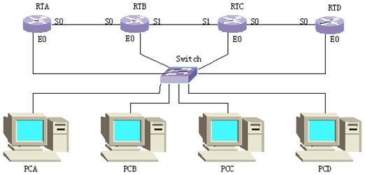
按照上图的实验组网建立实验环境。为了不受路由器原来的配置影响,在实验之前请先将所有路由器的配置数据擦除后重新启动。交换机在此只用作连接主机和路由器,以便全采用标准网线连接,不需要配置。
配置各主机和路由器接口的IP地址
各路由器的接口IP地址分配如下:
|
|
RTA |
RTB |
RTC |
RTD |
|
E0 |
202.0.0.1/24 |
202.0.1.1/24 |
202.0.2.1/24 |
202.0.3.1/24 |
|
S0 |
192.0.0.1/24 |
192.0.0.2/24 |
192.0.2.1/24 |
192.0.2.2/24 |
|
S1 |
|
192.0.1.1/24 |
192.0.1.2/24 |
|
各主机的IP地址和缺省网关分配如下:
|
|
PCA |
PCB |
PCC |
PCD |
|
IP |
202.0.0.2/24 |
202.0.1.2/24 |
202.0.2.2/24 |
202.0.3.2/24 |
|
Gateway |
202.0.0.1 |
202.0.1.1 |
202.0.2.1 |
202.0.3.1 |
启动路由协议及配置静态路由
在RTA与RTB之间配置静态路由,RTB与RTC之间启动RIP协议,RTC与RTD之间启动IGRP协议。具体使能哪些网段详见配置信息。在此,我们先不配置路由引入,看能否实现全网互通。配置好后,用show running-config命令查看配置信息如下:
路由器A的配置信息:
RTA#show running-config
Now create configuration...
Current configuration
!
version 1.5.6
logging console
hostname RTA
!
interface Aux0
async mode interactive
encapsulation ppp
!
interface Ethernet0
speed auto
duplex auto
no loopback
ip address 202.0.0.1 255.255.255.0
!
interface Serial0
encapsulation ppp
ip address 192.0.0.1 255.255.255.0
!
interface Serial1
encapsulation ppp
!
exit
ip route 0.0.0.0 0.0.0.0 192.0.0.2 preference 60
!
end
路由器B的配置信息:
RTB#show running-config
Now create configuration...
Current configuration
!
version 1.5.6
logging console
hostname RTB
!
interface Aux0
async mode interactive
encapsulation ppp
!
interface Ethernet0
speed auto
duplex auto
no loopback
ip address 202.0.1.1 255.255.255.0
!
interface Serial0
clock-select DTECLK1
encapsulation ppp
ip address 192.0.0.2 255.255.255.0
!
interface Serial1
clock-select DTECLK1
encapsulation ppp
ip address 192.0.1.1 255.255.255.0
!
exit
router rip
network 202.0.1.0
network 192.0.1.0
!
exit
ip route 202.0.0.0 255.255.255.0 192.0.0.1 preference 60
!
end
路由器C的配置信息:
RTC#show running-config
Now create configuration...
Current configuration
!
version 1.5.6
hostname RTC
!
interface Aux0
async mode interactive
encapsulation ppp
!
interface Ethernet0
speed auto
duplex auto
no loopback
ip address 202.0.2.1 255.255.255.0
!
interface Serial0
encapsulation ppp
ip address 192.0.2.1 255.255.255.0
!
interface Serial1
encapsulation ppp
ip address 192.0.1.2 255.255.255.0
!
exit
router rip
network 202.0.2.0
network 192.0.1.0
!
router igrp
network 202.0.2.0
network 192.0.2.0
!
end
路由器D的配置信息:
RTD#show running-config
Now create configuration...
Current configuration
!
version 1.5.6
hostname RTD
!
interface Aux0
async mode interactive
encapsulation ppp
!
interface Ethernet0
speed auto
duplex auto
no loopback
ip address 202.0.3.1 255.255.255.0
!
interface Serial0
encapsulation ppp
ip address 192.0.2.2 255.255.255.0
!
interface Serial1
encapsulation ppp
!
exit
router igrp
asystem 100
network 202.0.3.0
network 192.0.2.0
!
end
检查配置与以上配置相同后,用ping命令测试网络互通情况,我们会发现跨越路由器的网段不能互通,如202.0.0.0网段不能与202.0.2.0网段互通。在RTA上不能ping通192.0.2.0网段。这是由于不同路由协议发现的路由没有互相传递。通过查看路由器的路由信息可知不同路由协议之间没有相互交换路由信息,所以路由器不能发现整网的路由,从而不能全网互通。各路由器的路由表信息如示:
路由器A的路由表:
RTA#show ip route
Routing Tables:
Destination/Mask Proto Pref Metric Nexthop Interface
0.0.0.0/0 Static 60 0 192.0.0.2 Serial0
127.0.0.0/8 Direct 0 0 127.0.0.1 LoopBack0
127.0.0.1/32 Direct 0 0 127.0.0.1 LoopBack0
192.0.0.0/24 Direct 0 0 192.0.0.2 Serial0
192.0.0.1/32 Direct 0 0 127.0.0.1 LoopBack0
192.0.0.2/32 Direct 0 0 192.0.0.2 Serial0
202.0.0.0/24 Direct 0 0 202.0.0.1 Ethernet0
202.0.0.1/32 Direct 0 0 127.0.0.1 LoopBack0
路由器B的路由表:
RTB#show ip route
Routing Tables:
Destination/Mask Proto Pref Metric Nexthop Interface
127.0.0.0/8 Direct 0 0 127.0.0.1 LoopBack0
127.0.0.1/32 Direct 0 0 127.0.0.1 LoopBack0
192.0.0.0/24 Direct 0 0 192.0.0.1 Serial0
192.0.0.1/32 Direct 0 0 192.0.0.1 Serial0
192.0.0.2/32 Direct 0 0 127.0.0.1 LoopBack0
192.0.1.0/24 Direct 0 0 192.0.1.2 Serial1
192.0.1.1/32 Direct 0 0 127.0.0.1 LoopBack0
192.0.1.2/32 Direct 0 0 192.0.1.2 Serial1
202.0.0.0/24 Static 60 0 192.0.0.1 Serial0
202.0.1.0/24 Direct 0 0 202.0.1.1 Ethernet0
202.0.1.1/32 Direct 0 0 127.0.0.1 LoopBack0
202.0.2.0/24 RIP 100 1 192.0.1.2 Serial1
路由器C的路由表:
RTC#show ip route
Routing Tables:
Destination/Mask Proto Pref Metric Nexthop Interface
127.0.0.0/8 Direct 0 0 127.0.0.1 LoopBack0
127.0.0.1/32 Direct 0 0 127.0.0.1 LoopBack0
192.0.1.0/24 Direct 0 0 192.0.1.1 Serial1
192.0.1.1/32 Direct 0 0 192.0.1.1 Serial1
192.0.1.2/32 Direct 0 0 127.0.0.1 LoopBack0
192.0.2.0/24 Direct 0 0 192.0.2.2 Serial0
192.0.2.1/32 Direct 0 0 127.0.0.1 LoopBack0
192.0.2.2/32 Direct 0 0 192.0.2.2 Serial0
202.0.1.0/24 RIP 100 1 192.0.1.1 Serial1
202.0.2.0/24 Direct 0 0 202.0.2.1 Ethernet0
202.0.2.1/32 Direct 0 0 127.0.0.1 LoopBack0
202.0.3.0/24 IGRP 80 158300 192.0.2.2 Serial0
路由器D的路由表:
RTD#show ip route
Routing Tables:
Destination/Mask Proto Pref Metric Nexthop Interface
127.0.0.0/8 Direct 0 0 127.0.0.1 LoopBack0
127.0.0.1/32 Direct 0 0 127.0.0.1 LoopBack0
192.0.2.0/24 Direct 0 0 192.0.2.1 Serial0
192.0.2.1/32 Direct 0 0 192.0.2.1 Serial0
192.0.2.2/32 Direct 0 0 127.0.0.1 LoopBack0
202.0.2.0/24 IGRP 80 158300 192.0.2.1 Serial0
202.0.3.0/24 Direct 0 0 202.0.3.1 Ethernet0
202.0.3.1/32 Direct 0 0 127.0.0.1 LoopBack0
引入其它路由协议
为了实现全网互通,我们需要路由器能在不同协议之间交换路由信息或者全网运行同一种路由协议,但实际网络中往往需要运行多种路由协议,所以我们在这里有必要介绍如何让不同路由协议交换路由信息。这涉及到路由引入即引入其它路由协议发现的路由。下面是配置完路由引入后各路由器的配置信息和路由信息表:
路由器A:
RTA(config)#show running-config
Now create configuration...
Current configuration
!
version 1.5.6
logging console
hostname RTA
!
interface Aux0
async mode interactive
encapsulation ppp
!
interface Ethernet0
speed auto
duplex auto
no loopback
ip address 202.0.0.1 255.255.255.0
!
interface Serial0
encapsulation ppp
ip address 192.0.0.1 255.255.255.0
!
interface Serial1
encapsulation ppp
!
exit
ip route 0.0.0.0 0.0.0.0 192.0.0.2 preference 60
!
end
RTA(config)#show ip route
Routing Tables:
Destination/Mask Proto Pref Metric Nexthop Interface
0.0.0.0/0 Static 60 0 192.0.0.2 Serial0
127.0.0.0/8 Direct 0 0 127.0.0.1 LoopBack0
127.0.0.1/32 Direct 0 0 127.0.0.1 LoopBack0
192.0.0.0/24 Direct 0 0 192.0.0.2 Serial0
192.0.0.1/32 Direct 0 0 127.0.0.1 LoopBack0
192.0.0.2/32 Direct 0 0 192.0.0.2 Serial0
202.0.0.0/24 Direct 0 0 202.0.0.1 Ethernet0
202.0.0.1/32 Direct 0 0 127.0.0.1 LoopBack0
路由器B:
RTB# show running-config
Now create configuration...
Current configuration
!
version 1.5.6
logging console
hostname RTB
!
interface Aux0
async mode interactive
encapsulation ppp
!
interface Ethernet0
speed auto
duplex auto
no loopback
ip address 202.0.1.1 255.255.255.0
ip rip version 2 mcast
!
interface Serial0
clock-select DTECLK1
encapsulation ppp
ip address 192.0.0.2 255.255.255.0
!
interface Serial1
clock-select DTECLK1
encapsulation ppp
ip address 192.0.1.1 255.255.255.0
ip rip version 2 mcast
!
exit
router rip
network 192.0.1.0
network 202.0.1.0
redistribute connected metric 2 //引入直连路由;
redistribute static metric 2 //引入静态路由;
!
exit
ip route 202.0.0.0 255.255.255.0 192.0.0.1 preference 60
!
end
RTB# show ip route
Routing Tables:
Destination/Mask Proto Pref Metric Nexthop Interface
127.0.0.0/8 Direct 0 0 127.0.0.1 LoopBack0
127.0.0.1/32 Direct 0 0 127.0.0.1 LoopBack0
192.0.0.0/24 Direct 0 0 192.0.0.1 Serial0
192.0.0.1/32 Direct 0 0 192.0.0.1 Serial0
192.0.0.2/32 Direct 0 0 127.0.0.1 LoopBack0
192.0.1.0/24 Direct 0 0 192.0.1.2 Serial1
192.0.1.1/32 Direct 0 0 127.0.0.1 LoopBack0
192.0.1.2/32 Direct 0 0 192.0.1.2 Serial1
192.0.2.0/24 RIP 100 2 192.0.1.2 Serial1
202.0.0.0/24 Static 60 0 192.0.0.1 Serial0
202.0.1.0/24 Direct 0 0 202.0.1.1 Ethernet0
202.0.1.1/32 Direct 0 0 127.0.0.1 LoopBack0
202.0.2.0/24 RIP 100 1 192.0.1.2 Serial1
202.0.3.0/24 RIP 100 2 192.0.1.2 Serial1
路由器C:
RTC# show running-config
Now create configuration...
Current configuration
!
version 1.5.6
logging console
hostname RTC
!
interface Aux0
async mode interactive
encapsulation ppp
!
interface Ethernet0
speed auto
duplex auto
no loopback
ip address 202.0.2.1 255.255.255.0
ip rip version 2 mcast
!
interface Serial0
encapsulation ppp
ip address 192.0.2.1 255.255.255.0
!
interface Serial1
encapsulation ppp
ip address 192.0.1.2 255.255.255.0
ip rip version 2 mcast
!
exit
router rip
network 192.0.1.0
network 202.0.2.0
redistribute connected metric 2 //引入直连路由;
redistribute igrp metric 2 //引入IGRP协议路由;
!
router igrp
asystem 100
default-metric 2048 1000 100 100 1000 //设定缺省路有权;
network 192.0.2.0
network 202.0.2.0
redistribute connected metric 100 1000 100 100 1000 //引入直连路由;
redistribute rip //引入RIP协议路由;
!
end
RTC# show ip route
Routing Tables:
Destination/Mask Proto Pref Metric Nexthop Interface
127.0.0.0/8 Direct 0 0 127.0.0.1 LoopBack0
127.0.0.1/32 Direct 0 0 127.0.0.1 LoopBack0
192.0.0.0/24 RIP 100 2 192.0.1.1 Serial1
192.0.1.0/24 Direct 0 0 192.0.1.1 Serial1
192.0.1.1/32 Direct 0 0 192.0.1.1 Serial1
192.0.1.2/32 Direct 0 0 127.0.0.1 LoopBack0
192.0.2.0/24 Direct 0 0 192.0.2.2 Serial0
192.0.2.1/32 Direct 0 0 127.0.0.1 LoopBack0
192.0.2.2/32 Direct 0 0 192.0.2.2 Serial0
202.0.0.0/24 RIP 100 2 192.0.1.1 Serial1
202.0.1.0/24 RIP 100 1 192.0.1.1 Serial1
202.0.2.0/24 Direct 0 0 202.0.2.1 Ethernet0
202.0.2.1/32 Direct 0 0 127.0.0.1 LoopBack0
202.0.3.0/24 IGRP 80 158300 192.0.2.2 Serial0
路由器D:
RTD# show running-config
Now create configuration...
Current configuration
!
version 1.5.6
hostname RTD
!
interface Aux0
async mode interactive
encapsulation ppp
!
interface Ethernet0
speed auto
duplex auto
no loopback
ip address 202.0.3.1 255.255.255.0
!
interface Serial0
encapsulation ppp
ip address 192.0.2.2 255.255.255.0
!
interface Serial1
encapsulation ppp
!
exit
router igrp
asystem 100
network 192.0.2.0
network 202.0.3.0
!
end
RTD# show ip route
Routing Tables:
Destination/Mask Proto Pref Metric Nexthop Interface
127.0.0.0/8 Direct 0 0 127.0.0.1 LoopBack0
127.0.0.1/32 Direct 0 0 127.0.0.1 LoopBack0
192.0.0.0/24 IGRP 80 159200 192.0.2.1 Serial0
192.0.1.0/24 IGRP 80 159200 192.0.2.1 Serial0
192.0.2.0/24 Direct 0 0 192.0.2.1 Serial0
192.0.2.1/32 Direct 0 0 192.0.2.1 Serial0
192.0.2.2/32 Direct 0 0 127.0.0.1 LoopBack0
202.0.0.0/24 IGRP 80 159200 192.0.2.1 Serial0
202.0.1.0/24 IGRP 80 159200 192.0.2.1 Serial0
202.0.2.0/24 IGRP 80 158300 192.0.2.1 Serial0
202.0.3.0/24 Direct 0 0 202.0.3.1 Ethernet0
202.0.3.1/32 Direct 0 0 127.0.0.1 LoopBack0
从路由表可以看出,引入其他路由协议之后每个路由器的路由表都增加了几条新的路由记录,这就是通过路由引入从其他路由协议学习到的路由信息。现在我们再次测试全网的互通情况,会发现各网段的主机都可以互通了。