备份中心原理配置实验
7.1 实验目的:
1. 掌握备份中心的概念及功能;
2. 掌握物理接口作主接口的配置;
3. 掌握物理接口作备份接口的配置;
4. 掌握逻辑接口作主接口的配置;
5. 掌握逻辑接口作备份接口的配置。
7.2 实验环境:
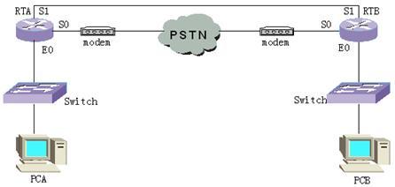
实验环境一,物理接口作主接口,dialer口作备份接口。实验组网如下:
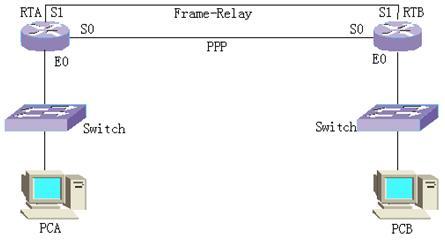
实验环境二,逻辑接口作主接口(帧中继的需电路),物理接口作备份接口。实验组网如下:
7.3 实验步骤:
7.3.1 物理接口作主接口,dialer口作备份接口
所有接口(Dialer口除外)都可以作主接口,所有接口都可以作备份接口对主接口进行备份。主接口还可以拥有多个备份接口,指定各备份接口的优先级来确定谁作为第一备份接口。下面我们来完成一个典型的实验,以便我们熟悉、掌握接口备份的配置。该实验使用实验环境一,路由器的S0口通过modem和PSTN网连接,S1口直接相连,封装成PPP。具体实验步骤如下:
1. 配置主接口;
2. 给主接口指定备份接口;
3. 配置备份接口;
4. 配置静态路由。
配置完成后的配置信息如下:
RTA#show running-config
Now create configuration...
Current configuration
!
version 1.5.6
dialer-list 1 protocol ip permit
logging console
hostname RTA
!
interface Aux0
async mode interactive
encapsulation ppp
!
interface Ethernet0
speed auto
duplex auto
no loopback
ip address 10.110.32.1 255.255.248.0
!
interface Serial0
physical-layer async
modem
async mode dedicated
encapsulation ppp
ip address 1.0.0.1 255.255.255.0
dialer in-band
dialer-group 1
dialer map ip 1.0.0.2 2342
!
interface Serial1
encapsulation ppp
backup interface Serial 0 //指定备份接口
ip address 2.0.0.1 255.255.255.0
!
exit
ip route 10.110.10.0 255.255.255.0 2.0.0.2 preference 60
ip route 10.110.10.0 255.255.255.0 1.0.0.2 preference 60
!
end
RTB#show running-config
Now create configuration...
Current configuration
!
version 1.5.6
dialer-list 1 protocol ip permit
hostname RTB
!
interface Aux0
async mode interactive
encapsulation ppp
!
interface Ethernet0
speed auto
duplex auto
no loopback
ip address 10.110.10.100 255.255.255.0
!
interface Serial0
physical-layer async
modem
async mode dedicated
encapsulation ppp
ip address 1.0.0.2 255.255.255.0
dialer in-band
dialer-group 1
dialer map ip 1.0.0.1 2342
!
interface Serial1
encapsulation ppp
ip address 2.0.0.2 255.255.255.0
!
exit
ip route 10.110.32.0 255.255.248.0 1.0.0.1 preference 60
ip route 10.110.32.0 255.255.248.0 2.0.0.1 preference 60
!
end
在配置时需要注意的是为主接口指定备份接口只需要在其中一端配置即可,并且是在主接口配置模式下配置的。同时必须配置静态路由指向不同的下一跳地址。完成上述配置之后,进行实验需求验证,首先测试网络是否能相互通信,如果能它是通过那一接口进行通信的,将该接口shutdown后,有什么现象出现?此时网络能相互通信吗?如果又将刚才的接口no shutdown有时什么现象呢?下面是完成上述操作的显示信息:
RTA(config-if-Serial1)#ping 10.110.10.100
PING 10.110.10.100: 56 data bytes, press CTRL_C to break
Reply from 10.110.10.100: bytes=56 Sequence=0 ttl=255 time = 27 ms
……
Reply from 10.110.10.100: bytes=56 Sequence=4 ttl=255 time = 27 ms
--- 10.110.10.100 ping statistics ---
5 packets transmitted
5 packets received
0.00% packet loss
round-trip min/avg/max = 27/27/28 ms
RTA(config-if-Serial1)#shutdown
% Interface Serial1 is shutdown
RTA(config-if-Serial1)#
% Interface Serial1 changed state to DOWN
% Line protocol ip on interface Serial1, changed state to DOWN
RTA(config-if-Serial1)#ping 10.110.10.100
PING 10.110.10.100: 56 data bytes, press CTRL_C to break
Request time out
……
Request time out
--- 10.110.10.100 ping statistics ---
5 packets transmitted
0 packets received
100.00% packet loss
RTA(config-if-Serial1)#
DDR: try to find routing to 1.0.0.2 on interface Serial0
DDR: it is an interesting packet
DDR: Find a dialer map matching the address
DDR: Try to find a free channel to dial 2342: on the interface
DDR: Dialing 2342 on interface Serial0 of interface Serial0
DDR: discard this packet
DDR: try to find routing to 1.0.0.2 on interface Serial0
DDR: it is an interesting packet
DDR: Find a dialer map matching the address
DDR: A Link is connecting by this dialer map, waiting this Link
DDR: discard this packet
……
% Interface Serial0 changed state to UP
%MODEM: Serial0 changed state to UP.
DDR: Receive CALL_CONN_CFM
DDR: link layer ask the PPP_interface of the interface Serial0
DDR: Link layer transfer NAME '' to DDR on interface Serial0
DDR: NAME authentication OK
% Line protocol ip on interface Serial0, changed state to UP
DDR: link negotiation Up on interface Serial0
DDR: peeraddr matching success on interface Serial0 ,link UP
RTA(config-if-Serial1)#ping 10.110.10.100
PING 10.110.10.100: 56 data bytes, press CTRL_C to break
Reply from 10.110.10.100: bytes=56 Sequence=0 ttl=255 time = 499 ms
……
Reply from 10.110.10.100: bytes=56 Sequence=4 ttl=255 time = 476 ms
--- 10.110.10.100 ping statistics ---
5 packets transmitted
5 packets received
0.00% packet loss
round-trip min/avg/max = 476/482/499 ms
RTA(config-if-Serial1)#
DDR: try to find routing to 1.0.0.2 on interface Serial0
DDR: it is an interesting packet
DDR: Find a Up Link on interface Serial0, success!
……
RTA(config-if-Serial1)#no shutdown
% Interface Serial1 is reset
RTA(config-if-Serial1)#
% Interface Serial1 changed state to UP
% Line protocol ip on interface Serial1, changed state to UP
% Line protocol ip on interface Serial0, changed state to DOWN
DDR: Receive CALL_DISC_IND, shutdown link, start enable-timeout
DDR: link negotiation Down on interface Serial0
RTA(config-if-Serial1)#ping 10.110.10.100
PING 10.110.10.100: 56 data bytes, press CTRL_C to break
Reply from 10.110.10.100: bytes=56 Sequence=0 ttl=255 time = 27 ms
……
Reply from 10.110.10.100: bytes=56 Sequence=4 ttl=255 time = 27 ms
--- 10.110.10.100 ping statistics ---
5 packets transmitted
5 packets received
0.00% packet loss
round-trip min/avg/max = 27/27/28 ms
从这个过程可以看出,dialer口起到了良好的备份作用。当主接口故障时,备份接口代替主接口完成通信,当主接口恢复正常后,通信自动切换到主接口。如果我们主接口或是备份接口的传输线路不稳定,那么在主备接口之间频频发生切换也是不现实的。那么我们怎么来控制它呢?Quidway路由器为我们提供了控制接口切换的功能(backup delay),缺省情况下,主接口切换到备份接口的延时值enable-delay为0秒(立即切换),备份接口切换到主接口的延时值disable-delay也为0秒,取值范围都是0-65535秒。您可以修改该参数,看看实验现象与您的要求一致吗?注意:如果有多个备份接口,在指定时一定要指定它们的优先级。
7.3.2 逻辑接口作主接口,物理接口作备份接口
我们在前面提到所有接口都可以作主接口,那么逻辑接口作主接口有时怎么配置的呢?其实配置与上一实验配置相似,只是需要给需电路分配一逻辑通道号。我们采用实验环境二,具体实验步骤不再详述,下面时完成后的配置信息:
RTA#show running-config
Now create configuration...
Current configuration
!
version 1.5.6
hostname RTA
!
interface Aux0
async mode interactive
encapsulation ppp
!
interface Ethernet0
speed auto
duplex auto
no loopback
ip address 10.110.32.1 255.255.248.0
!
interface Serial0
clock-select DTECLK1
encapsulation ppp
ip address 1.0.0.1 255.255.255.0
!
interface Serial1
encapsulation frame-relay
frame-relay local-dlci 100
frame-relay map ip 2.0.0.2 100 lin 10 //给虚礼电路分配逻辑通道号
ip address 2.0.0.1 255.255.255.0
!
logic-channel 10
backup interface Serial 0 //指定备份接口
!
exit
ip route 10.110.10.0 255.255.255.0 2.0.0.2 preference 60
ip route 10.110.10.0 255.255.255.0 1.0.0.2 preference 60
!
end
RTA#
RTB(config)#show running-config
Now create configuration...
Current configuration
!
version 1.5.6
hostname RTB
frame-relay switching
!
interface Aux0
async mode interactive
encapsulation ppp
!
interface Ethernet0
speed auto
duplex auto
no loopback
ip address 10.110.10.100 255.255.255.0
!
interface Serial0
encapsulation ppp
ip address 1.0.0.2 255.255.255.0
!
interface Serial1
encapsulation frame-relay
frame-relay intf-type DCE
frame-relay local-dlci 100
frame-relay map ip 2.0.0.1 100 lin 10
ip address 2.0.0.2 255.255.255.0
!
logic-channel 10
!
exit
ip route 10.110.32.0 255.255.248.0 1.0.0.1 preference 60
ip route 10.110.32.0 255.255.248.0 2.0.0.1 preference 60
!
end
完成上述配置后,同上一个实验一样验证是否满足实验需求,比较两次实验是否有差异?前面提到过接口切换的配置,在此逻辑接口作主接口时,配置切换条件有些区别。判断主逻辑接口通道down的条件是呼叫失败次数,超过设定的次数则认为主逻辑接口down,此时才进行切换。使用的命令为backup state-down number。判断主接口是否恢复up,是通过设定间隔时间interval-time来定期检查实现的。使用的命令为backup state-up interval-time。请您自行修改参数并验证该功能。
其他情况的备份都可以仿照上面的实验进行配置,在此不再赘述。
小结
本实验主要是让我们掌握Quidway路由器的备份功能,各种接口之间的备份配置。内容比较简单,但仔细总结仍会有较大收获的。