晕……搞成“小说连载”了!
广域网协议配置实验
4.1实验目的:
1. 掌握PPP协议的基本原理及基本配置;
2. 掌握PPP验证原理及过程以及两种验证方式的配置;
3. 熟悉MP协议的基本原理和基本配置;
4. 掌握X.25协议的基本原理和基本配置;
5. 掌握帧中继的基本原理和基本配置;
6. 熟悉帧中继子接口的配置;
7. 掌握在广域网协议上配置RIP协议。
4.2实验环境:
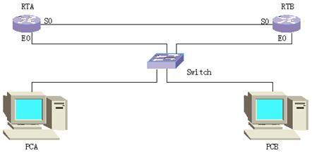
在实验室中,没有真正的广域网存在。为了让我们完成相关实验,我们采用背靠背的连接来模拟广域网。实验模拟环境如下:
为了保证配置不受影响,请在实验之前清除路由器的所有配置后重新启动。
4.3实验步骤:
4.3.1 PPP协议
PPP协议是广泛应用的广域网协议,也是最简单,最基本的广域网协议。华为路由器的同异步串口上的缺省封装也采用PPP协议,所以我们首先研究一下PPP协议。
配置路由器的接口IP地址和主机的IP地址及缺省网关
路由器的接口IP地址分配如下:
|
|
RTA |
RTB |
|
E0 |
202.0.0.1/24 |
202.0.1.1/24 |
|
S0 |
192.0.0.1/24 |
192.0.0.2/24 |
主机(PC)IP地址和Gateway分配如下:
|
|
PCA |
PCB |
|
IP |
202.0.0.2/24 |
202.0.1.2/24 |
|
Gateway |
202.0.0.1 |
202.0.1.1 |
配置完接口IP地址和主机地址,修改路由器名称后显示RTA的配置信息和路由表信息如下:
RTA#show running-config
Now create configuration...
Current configuration
!
version 1.5.6
hostname RTA
!
interface Aux0
async mode interactive
encapsulation ppp
!
interface Ethernet0
speed auto
duplex auto
no loopback
ip address 202.0.0.1 255.255.255.0
!
interface Serial0
encapsulation ppp
ip address 192.0.0.1 255.255.255.0
!
interface Serial1
encapsulation ppp
!
end
RTA(config-if-Serial0)#show ip route
Routing Tables:
Destination/Mask Proto Pref Metric Nexthop Interface
127.0.0.0/8 Direct 0 0 127.0.0.1 LoopBack0
127.0.0.1/32 Direct 0 0 127.0.0.1 LoopBack0
192.0.0.0/24 Direct 0 0 192.0.0.2 Serial0
192.0.0.1/32 Direct 0 0 127.0.0.1 LoopBack0
192.0.0.2/32 Direct 0 0 192.0.0.2 Serial0
202.0.0.0/24 Direct 0 0 202.0.0.1 Ethernet0
202.0.0.1/32 Direct 0 0 127.0.0.1 LoopBack0
RTB的相关信息类似RTA。从配置信息可以看出我们还没有在接口上封装广域网协议,但实际上已经被封装了PPP协议,这就是华为路由器的缺省封装。
配置PPP协议验证
PPP验证有PAP验证和CHAP验证两种,前者是明文验证,后者是密文认证。具体工作原理详见教材。配置验证时,一般采用单向验证即可,也可以配置双向验证。在此我们配置单向验证。RTA作为主验证方,RTB为被验证方。在配置中要注意双方的密码必须一致且区分大小写,在配置完成后,需要在接口上shutdown和no shutdown使之生效才能检测是否配置正确。配置完PAP验证并启动RIP协议后的show running-config信息如下:
RTA(config-if-Serial0)#show running-config
Now create configuration...
Current configuration
!
version 1.5.6
user RTB service-type ppp password 0 aaa //配置用户列表
logging console
hostname RTA
!
interface Aux0
async mode interactive
encapsulation ppp
!
interface Ethernet0
speed auto
duplex auto
no loopback
ip address 202.0.0.1 255.255.255.0
!
interface Serial0
encapsulation ppp
ppp authentication pap //授权PAP验证
ip address 192.0.0.1 255.255.255.0
!
interface Serial1
encapsulation ppp
!
exit
router rip //启动RIP协议
network all //使能各网段
!
end
RTB(config-if-Serial0)#show running-config
Now create configuration...
Current configuration
!
version 1.5.6
logging console
hostname RTB
!
interface Aux0
async mode interactive
encapsulation ppp
!
interface Ethernet0
speed auto
duplex auto
no loopback
ip address 202.0.1.1 255.255.255.0
!
interface Serial0
clock-select DTECLK1
encapsulation ppp
ppp pap sent-username RTB password 0 aaa //配置PAP用户名
ip address 192.0.0.2 255.255.255.0
!
interface Serial1
encapsulation ppp
!
exit
router rip
network all
!
end
如果配置正确,显示接口信息,会发现IPCP opened。如果配置有误,验证没有通过会有IPCP initial。下面是验证通过时的接口信息:
RTA(config-if-Serial0)#show interface serial 0
Serial0 is up, line protocol is up
physical layer is synchronous, baudrate is 64000 bps
interface is DCE, clock is DCECLK, cable type is V35
Internet address is 192.0.0.1 255.255.255.0
Encapsulation is PPP
LCP opened, IPCP opened, IPXCP initial, CCP initial
5 minutes input rate 6.67 bytes/sec, 0.27 packets/sec
5 minutes output rate 6.61 bytes/sec, 0.27 packets/sec
Input queue :(size/max/drops)
0/50/0
Queueing strategy: FIFO
Output Queue :(size/max/drops)
0/50/0
342 packets input, 8312 bytes, 0 no buffers
341 packets output, 8332 bytes, 0 no buffers
0 input errors, 0 CRC, 0 frame errors
0 overrunners, 0 aborted sequences, 0 input no buffers
DCD=UP DTR=UP DSR=UP RTS=UP CTS=UP
配置完CHAP验证之后的show running-config信息:
RTA(config-if-Serial0)#show running-config
Now create configuration...
Current configuration
!
version 1.5.6
user RTB service-type ppp password 0 aaa
logging console
hostname RTA
!
interface Aux0
async mode interactive
encapsulation ppp
!
interface Ethernet0
speed auto
duplex auto
no loopback
ip address 202.0.0.1 255.255.255.0
!
interface Serial0
encapsulation ppp
ppp authentication chap //授权CHAP验证
ppp chap host RTA //配置本地名称
ip address 192.0.0.1 255.255.255.0
!
interface Serial1
encapsulation ppp
!
exit
router rip
network all
!
end
RTB(config)# show running-config
Now create configuration...
Current configuration
!
version 1.5.6
user RTA service-type ppp password 0 aaa
logging console
hostname RTB
!
interface Aux0
async mode interactive
encapsulation ppp
!
interface Ethernet0
speed auto
duplex auto
no loopback
ip address 202.0.1.1 255.255.255.0
!
interface Serial0
clock-select DTECLK1
encapsulation ppp
ppp chap host RTB
ip address 192.0.0.2 255.255.255.0
!
interface Serial1
encapsulation ppp
!
exit
router rip
network all
!
end
该实验配置简单,但涉及的原理非常重要,在完成实验时一定要掌握两种验证的原理和工作方式以及两者的异同。
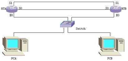
Multilink PPP
由于串口的带宽有限,需要增加带宽时,人们想到了将多个PPP链路捆绑使用来增加带宽即Multilink PPP,简称MP。为了让我们深入理解MP,我们来完成下面的实验,实验中两台路由器的两个串口分别背靠背连接。模拟实验环境如下:
具体实验步骤如下:
1. 增加用户;
2. 创建虚拟接口模板;
3. 将接口加入MP通道;
4. 为用户指定虚拟接口模板;
5. 配置CHAP验证。(注意:在MP中要求配置双方验证)
完成上述步骤之后,显示RTA配置信息如下:(RTB类似RTA)
TRA#show running-config
Now create configuration...
Current configuration
!
version 1.5.6
user rtb service-type ppp password 0 aaa //增加用户
multilink-user rtb bind Virtual-Template1 //为用户指定虚拟接口模板
hostname TRA
!
interface Aux0
async mode interactive
encapsulation ppp
!
interface Ethernet0
speed auto
duplex auto
no loopback
ip address 202.0.0.1 255.255.255.0
!
interface Serial0
encapsulation ppp //封装PPP
ppp authentication chap //授权验证
ppp multilink //加入MP通道
ppp chap host rta //配置本地名称
!
interface Serial1
encapsulation ppp
ppp authentication chap
ppp multilink
ppp chap host rta
!
interface Virtual-Template1 //创建虚拟接口模板
ip address 192.0.0.1 255.255.255.0 //配置虚拟接口模板的工作参数
!
exit
router rip
network all
!
end
完成上述配置之后,各接口和主机应该能够相互ping通。在配置MP之后,打开PPP调试开关,我们还可以看到如下调试信息:
RTB#debug ppp packet
PPP packet debug flag is on
PPP-MP: Serial0 O Pkts, flag BE, SeqNumber 27
Serial0
PPP O MP(003d) Pkt, Len 62, Flag BE, SeqNum 26
Serial1
PPP I MP(003d) Pkt, Len 62, Flag BE, SeqNum 25
从调试信息可以知道S0,S1工作在MP方式下。
4.3.2 X.25协议
X.25协议是数据终端设备(DTE)和数据电路终结设备(DCE)之间的接口规程。它分为分组层、数据链路层、物理层三层,而PPP协议只有两层,所以在配置上也存在许多差异,在实验中我们应该多加比较总结。下面我们来完成如下实验,以便深入了解X.25协议。实验环境仍采用PPP实验的模拟环境,初始配置都一样。然后在接口上封装X.25协议和启动RIP协议,完成配置后显示配置信息如下:
RTA#show running-config
Now create configuration...
Current configuration
!
version 1.5.6
hostname RTA
!
interface Aux0
async mode interactive
encapsulation ppp
!
interface Ethernet0
speed auto
duplex auto
no loopback
ip address 202.0.0.1 255.255.255.0
!
interface Serial0
encapsulation x25 dce ietf //封装X.25协议,接口类型为DCE,封装格式为IETF
x25 address 20021000010000 //配置接口的X.121地址
x25 map ip 192.0.0.2 20021000010001 //创建地址映射
ip address 192.0.0.1 255.255.255.0
!
interface Serial1
encapsulation ppp
!
exit
router rip
network all
neighbor 192.0.0.2 //配置邻居
!
end
RTB#show running-config
Now create configuration...
Current configuration
!
version 1.5.6
hostname RTB
!
interface Aux0
async mode interactive
encapsulation ppp
!
interface Ethernet0
speed auto
duplex auto
no loopback
ip address 202.0.1.1 255.255.255.0
!
interface Serial0
clock-select DTECLK1
encapsulation x25 dte ietf
x25 address 20021000010001
x25 map ip 192.0.0.1 20021000010000
ip address 192.0.0.2 255.255.255.0
!
interface Serial1
encapsulation ppp
!
exit
router rip
network all
neighbor 192.0.0.1
!
end
在配置信息中可以看出两端接口封装的类型不同,比PPP协议多了地址映射,少了验证功能,并且在配置动态路由协议时,也多了neighbor命令。要多注意这些区别。
注意事项:
动态路由协议的配置,如果不配置neighbor命令路由器间是不能交换路由信息的,您可以自己验证一下。
配置地址映射时,其中的IP地址和X.121地址都是对端的地址。
配置接口类型时,由于是背靠背连接,必须一端为DCE,另一端为DTE。实际组网时通常中间经过了X.25网络,所以不需要封装DCE设备。
在实际组网配置中,X.25的分组层参数一般都不需要改变,使用默认值即可。但在某些特殊情况下仍需要修改,修改的配置命令都比较简单,在这里不再赘述,您可以自行练习,但要注意最好保持两端的参数一致,否则容易丢包。我们可以从接口信息中查看分组层的参数默认值或者是新配置的值。下面是华为路由器的默认配置参数:(黑体是我们关注的信息)
RTB#show interface serial 0
Serial0 is up, line protocol is up
physical layer is synchronous
interface is DTE, clock is DTECLK1, cable type is V35
Internet address is 192.0.0.2 255.255.255.0
Encapsulation X.25 DTE ietf, address is 20021000010001, state Ready, modulo 8
input/output: window sizes 2/2, packet sizes 128/128
Channels: Incoming-only 0-0, Two-way 1-1024, Outgoing-only 0-0
Timers: T20 180, T21 200, T22 180, T23 180, T28 300, Idle_Timer 0 (seconds)
New configuration(will be effective after restart): modulo 8
input/output: window sizes 2/2, packet sizes 128/128
Channels: Incoming-only 0-0, Two-way 1-1024, Outgoing-only 0-0
Statistic: Restarts 5 (Restart Collisions 5)
Refused Incoming Call 0, Failing Outgoing Call 0
input/output: RESTART 5/5 CALL 3/5 DIAGNOSE 0/0
DATA 415/411 INTERRUPT 0/0 Bytes 11820/11716
RR 2/2 RNR 0/0 REJ 0/0
Invalid Pr: 0 Invalid Ps: 0 Unknown: 0
LAPB DTE, module 8, k 7, N1 12056, N2 10
timer: T1 2000, T2 1000, T3 0 (milliseconds)
state CONNECT, VS 4, VR 4, Remote VR 4
IFRAME 231/229, RR 7/199, RNR 0/0, REJ 0/0
FRMR 0/0, SABM 4/13, DM 0/0, UA 1/4
DISC 0/0, invalid ns 0, invalid nr 0, link resets 1
5 minutes input rate 2.08 bytes/sec, 0.05 packets/sec
5 minutes output rate 2.21 bytes/sec, 0.09 packets/sec
Input queue :(size/max/drops)
0/50/0
Queueing strategy: FIFO
Output Queue :(size/max/drops)
0/50/0
896 packets input, 24659 bytes, 0 no buffers
475 packets output, 13805 bytes, 0 no buffers
0 input errors, 0 CRC, 0 frame errors
0 overrunners, 0 aborted sequences, 0 input no buffers
DCD=UP DTR=UP DSR=UP RTS=UP CTS=UP
4.3.3 Frame-relay 协议
帧中继协议是在X.25分组交换技术的基础上发展起来的一种快速分组交换技术,即是在数据链路层用简化的方法转发和交换数据单元的快速分组交换技术。帧中继相对于X.25来说简单而高效,所以它正在代替传统的复杂低速的报文交换服务。为了能较快掌握理解帧中继,我们来进行如下实验。实验环境和初始配置同PPP实验。实验步骤大致如下:
1. 封装接口;
2. 配置帧中继接口的终端类型;
3. 选择LMI类型;
4. 在DCE上分配DLCI;
5. 启动inverse-arp逆向地址解析协议(默认已经启动);
6. 启动RIP协议。
完成上述配置之后,显示配置信息如下:
RTA#show running-config
Now create configuration...
Current configuration
!
version 1.5.6
hostname RTA
!
interface Aux0
async mode interactive
encapsulation ppp
!
interface Ethernet0
speed auto
duplex auto
no loopback
ip address 202.0.0.1 255.255.255.0
!
interface Serial0
encapsulation frame-relay //封装帧中继接口
ip address 192.0.0.1 255.255.255.0
!
interface Serial1
encapsulation ppp
!
exit
router rip
network all
neighbor 192.0.0.2
!
end
RTB#show run
Now create configuration...
Current configuration
!
version 1.5.6
logging console
hostname RTB
frame-relay switching //使能帧中继交换
!
interface Aux0
async mode interactive
encapsulation ppp
!
interface Ethernet0
speed auto
duplex auto
no loopback
ip address 202.0.1.1 255.255.255.0
!
interface Serial0
clock-select DTECLK1
encapsulation frame-relay
frame-relay intf-type DCE //封装帧中继接口类型
frame-relay local-dlci 20 //为接口分配DLCI
ip address 192.0.0.2 255.255.255.0
!
interface Serial1
encapsulation ppp
!
exit
router rip
network all
neighbor 192.0.0.1
!
end
在上述配置信息中,有部分信息没有显示出来,那是由于华为路由器有默认配置,当我们的配置与默认配置相同时,在show-running-config信息中就不会显示。与X.25相比,帧中继启动RIP协议同样需要配置neighbor命令;但要将接口封装成DCE设备,必须先使能帧中继交换;在接口上可以不配置地址映射,只需要在DCE侧分配DLCI值即可。这是因为帧中继支持逆向地址解析协议(inverse ARP),它可以动态的建立MAP。您可以查看帧中继的地址映射表看到如下信息:
RTA#show frame-relay map
Serial0(protocol is up):
ip 192.0.0.2 dlci 20 (0x14), dynamic,
IETF, status active
RTB#show frame-relay map
Serial0(protocol is up):
ip 192.0.0.1 dlci 20 (0x14), dynamic,
IETF, status active
当然,我们也可以手工建立地址映射,为了能让我们确认我们的配置是否正确,请你先在两侧路由器上关闭逆向地址解析协议功能(no frame-relay inverse-arp)。然后分别给各接口分配DLCI值,最后手工创建地址映射(frame-relay map ip ip-address dlci),其中ip-address是对端的IP地址,dlci是对端设备的帧中继地址(实际上是本端的DLCI)。完成上述配置之后,再次查看帧中继地址映射表可以看到如下信息:
RTA#show frame-relay map
Serial0(protocol is up):
ip 192.0.0.2 dlci 20 (0x14), static,
IETF, status active
RTB#show frame-relay map
Serial0(protocol is up):
ip 192.0.0.1 dlci 20 (0x14), static,
IETF, status active
此时测试网络互通性,应该是正常的。您还可以去掉手工创建的地址映射后,再看看地址映射表里面有没有地址映射项。此时网络还通吗?
帧中继子接口
在帧中继中,为了解决水平分割带来的影响,增加了新的功能,那就是子接口。可以在一个物理接口上创建多个子接口分别连接不同的子网路由器,每个子接口都有自己的网络地址,相当于独立的物理接口,这就解决了水平分割带来的影响。为了掌握它,我们来完成如下实验。模拟实验环境需要四台路由器,一台PC即可,PC作配置用。实验组网如下:
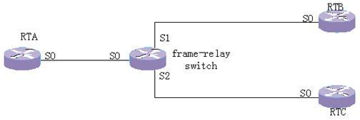
图中,中间一台路由器用作帧中继交换使用,需要多个串口,如果在实验室没有多串口路由器,可以减少一个路由器RTC就可以完成实验了。
实验步骤:
1. 配置帧中继交换机,使能帧中继交换,配置帧中继接口类型,配置PVC路由;
2. 在RTA上创建子接口,分配DLCI,创建地址映射,配置IP地址;
3. 在RTB、RTC上分配DLCI,创建地址映射,配置IP地址。
完成上述配置后,显示配置信息如下:
RTA#show running-config
Now create configuration...
Current configuration
!
version 1.5.6
hostname RTA
!
interface Serial0
encapsulation frame-relay
!
interface Serial0.1 MultiPoint //创建子接口
frame-relay map ip 192.0.0.2 300 //建立地址映射
frame-relay interface-dlci 300 //分配DLCI
ip address 192.0.0.1 255.255.255.0
!
interface Serial0.2 MultiPoint
frame-relay map ip 192.0.1.2 400
frame-relay interface-dlci 400
ip address 192.0.1.1 255.255.255.0
!
interface Serial1
encapsulation ppp
!
end
RTB# show running-config
Now create configuration...
Current configuration
!
version 1.5.6
hostname RTB
!
interface Serial0
encapsulation frame-relay
frame-relay local-dlci 100
frame-relay map ip 192.0.0.1 100
ip address 192.0.0.2 255.255.255.0
!
interface Serial1
encapsulation ppp
!
end
RTC# show running-config
Now create configuration...
Current configuration
!
version 1.5.6
hostname RTC
!
interface Serial0
encapsulation frame-relay
frame-relay local-dlci 200
frame-relay map ip 192.0.1.1 200
ip address 192.0.1.2 255.255.255.0
!
interface Serial1
encapsulation ppp
!
end
frame-relay switch# show running-config
Now create configuration...
Current configuration
!
version 1.5.6
frame-relay switching //使能帧中继交换
!
interface Serial0
clock-select DTECLK1
encapsulation frame-relay
frame-relay intf-type DCE
frame-relay route 300 interface Serial 1 100 //配置PVC交换路由
frame-relay route 400 interface Serial 2 200
!
interface Serial1
encapsulation frame-relay
frame-relay intf-type DCE
frame-relay route 100 interface Serial 0 300
!
interface Serial2
clock-select DTECLK3
encapsulation frame-relay
frame-relay intf-type DCE
frame-relay route 200 interface Serial 0 400
!
end
现在可以在各个接口测试网络互通性了。如果配置完全正确,就应该能够ping通。另外,在各个接口上的DLCI是可以重复的,即只要在本接口没有重复的DLCI即可。现在我们完成了各个功能性实验,如果有时间请完成下面的综合实验,进一步提高大家的技能。
4.3.4 综合实验
现在我们已经完成了几种广域网协议的功能性试验,为了我们能够较好的比较上述几种协议在原理和配置上的区别,我们来完成下面的实验,在该实验中启动了三种广域网协议即PPP,X.25,Frame-relay。实验环境如下:
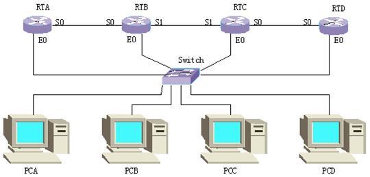
按照上图的实验组网建立实验环境。为了不受路由器原来的配置影响,在实验之前请先将所有路由器的配置数据擦除后重新启动。交换机在此只用作连接主机和路由器用,以便全采用标准网线连接,不需要配置。
配置各主机和路由器接口的IP地址
各路由器的接口IP地址分配如下:
|
|
RTA |
RTB |
RTC |
RTD |
|
E0 |
202.0.0.1/24 |
202.0.1.1/24 |
202.0.2.1/24 |
202.0.3.1/24 |
|
S0 |
192.0.0.1/24 |
192.0.0.2/24 |
192.0.2.1/24 |
192.0.2.2/24 |
|
S1 |
|
192.0.1.1/24 |
192.0.1.2/24 |
|
各主机的IP地址和缺省网关分配如下:
|
|
PCA |
PCB |
PCC |
PCD |
|
IP |
202.0.0.2/24 |
202.0.1.2/24 |
202.0.2.2/24 |
202.0.3.2/24 |
|
Gateway |
202.0.0.1 |
202.0.1.1 |
202.0.2.1 |
202.0.3.1 |
配置广域网协议
在RTA和RTB之间配置PPP协议,在RTB和RTC之间配置X.25协议,在RTC和RTD之间配置frame-relay协议,并在所有路由器上启动路由协议并使能所有接口。注意:在X.25、frame-relay协议上启动RIP协议必须配置neighbor命令,否则不能正常工作。但在PPP协议上可以不配置。完成上述配置后显示路由器配置信息和路由表信息分别如下:
RTA的相关信息:
RTA#show running-config
Now create configuration...
Current configuration
!
version 1.5.6
logging console
hostname RTA
!
interface Aux0
async mode interactive
encapsulation ppp
!
interface Ethernet0
speed auto
duplex auto
no loopback
ip address 202.0.0.1 255.255.255.0
!
interface Serial0
encapsulation ppp
ip address 192.0.0.1 255.255.255.0
!
interface Serial1
encapsulation ppp
!
exit
router rip
network all
!
end
RTA#show ip route
Routing Tables:
Destination/Mask Proto Pref Metric Nexthop Interface
127.0.0.0/8 Direct 0 0 127.0.0.1 LoopBack0
127.0.0.1/32 Direct 0 0 127.0.0.1 LoopBack0
192.0.0.0/24 Direct 0 0 192.0.0.2 Serial0
192.0.0.1/32 Direct 0 0 127.0.0.1 LoopBack0
192.0.0.2/32 Direct 0 0 192.0.0.2 Serial0
192.0.1.0/24 RIP 100 1 192.0.0.2 Serial0
192.0.2.0/24 RIP 100 2 192.0.0.2 Serial0
202.0.0.0/24 Direct 0 0 202.0.0.1 Ethernet0
202.0.0.1/32 Direct 0 0 127.0.0.1 LoopBack0
202.0.1.0/24 RIP 100 1 192.0.0.2 Serial0
202.0.2.0/24 RIP 100 2 192.0.0.2 Serial0
202.0.3.0/24 RIP 100 3 192.0.0.2 Serial0
RTB的相关信息:
RTB# show running-config
Now create configuration...
Current configuration
!
version 1.5.6
logging console
hostname RTB
!
interface Aux0
async mode interactive
encapsulation ppp
!
interface Ethernet0
speed auto
duplex auto
no loopback
ip address 202.0.1.1 255.255.255.0
!
interface Serial0
clock-select DTECLK1
encapsulation ppp
ip address 192.0.0.2 255.255.255.0
!
interface Serial1
clock-select DTECLK1
encapsulation x25 dte ietf
x25 address 20001000020001
x25 map ip 192.0.1.2 20001000020002
ip address 192.0.1.1 255.255.255.0
!
exit
router rip
network all
neighbor 192.0.1.2
!
end
RTB#show ip route
Routing Tables:
Destination/Mask Proto Pref Metric Nexthop Interface
127.0.0.0/8 Direct 0 0 127.0.0.1 LoopBack0
127.0.0.1/32 Direct 0 0 127.0.0.1 LoopBack0
192.0.0.0/24 Direct 0 0 192.0.0.1 Serial0
192.0.0.1/32 Direct 0 0 192.0.0.1 Serial0
192.0.0.2/32 Direct 0 0 127.0.0.1 LoopBack0
192.0.1.0/24 Direct 0 0 192.0.1.1 Serial1
192.0.1.1/32 Direct 0 0 127.0.0.1 LoopBack0
192.0.2.0/24 RIP 100 1 192.0.1.2 Serial1
202.0.0.0/24 RIP 100 1 192.0.0.1 Serial0
202.0.1.0/24 Direct 0 0 202.0.1.1 Ethernet0
202.0.1.1/32 Direct 0 0 127.0.0.1 LoopBack0
202.0.2.0/24 RIP 100 1 192.0.1.2 Serial1
202.0.3.0/24 RIP 100 2 192.0.1.2 Serial1
RTC的相关信息:
RTC# show running-config
Now create configuration...
Current configuration
!
version 1.5.6
logging console
hostname RTC
!
interface Aux0
async mode interactive
encapsulation ppp
!
interface Ethernet0
speed auto
duplex auto
no loopback
ip address 202.0.2.1 255.255.255.0
!
interface Serial0
encapsulation frame-relay
frame-relay lmi-type ansi
frame-relay local-dlci 100
frame-relay map ip 192.0.2.2 200
ip address 192.0.2.1 255.255.255.0
!
interface Serial1
encapsulation x25 dce ietf
x25 address 20001000020002
x25 map ip 192.0.1.1 20001000020001
ip address 192.0.1.2 255.255.255.0
!
exit
router rip
network all
neighbor 192.0.2.2
neighbor 192.0.1.1
!
end
RTC#show ip route
Routing Tables:
Destination/Mask Proto Pref Metric Nexthop Interface
127.0.0.0/8 Direct 0 0 127.0.0.1 LoopBack0
127.0.0.1/32 Direct 0 0 127.0.0.1 LoopBack0
192.0.0.0/24 RIP 100 1 192.0.1.1 Serial1
192.0.1.0/24 Direct 0 0 192.0.1.2 Serial1
192.0.1.2/32 Direct 0 0 127.0.0.1 LoopBack0
192.0.2.0/24 Direct 0 0 192.0.2.1 Serial0
192.0.2.1/32 Direct 0 0 127.0.0.1 LoopBack0
202.0.0.0/24 RIP 100 2 192.0.1.1 Serial1
202.0.1.0/24 RIP 100 1 192.0.1.1 Serial1
202.0.2.0/24 Direct 0 0 202.0.2.1 Ethernet0
202.0.2.1/32 Direct 0 0 127.0.0.1 LoopBack0
202.0.3.0/24 RIP 100 1 192.0.2.2 Serial0
RTD的相关信息:
RTD# show running-config
Now create configuration...
Current configuration
!
version 1.5.6
hostname RTD
frame-relay switching
!
interface Aux0
async mode interactive
encapsulation ppp
!
interface Ethernet0
speed auto
duplex auto
no loopback
ip address 202.0.3.1 255.255.255.0
!
interface Serial0
encapsulation frame-relay
frame-relay lmi-type ansi
frame-relay intf-type DCE
frame-relay local-dlci 200
frame-relay map ip 192.0.2.1 100
ip address 192.0.2.2 255.255.255.0
!
interface Serial1
encapsulation ppp
!
exit
router rip
network all
neighbor 192.0.2.1
!
end
RTD#show ip route
Routing Tables:
Destination/Mask Proto Pref Metric Nexthop Interface
127.0.0.0/8 Direct 0 0 127.0.0.1 LoopBack0
127.0.0.1/32 Direct 0 0 127.0.0.1 LoopBack0
192.0.0.0/24 RIP 100 2 192.0.2.1 Serial0
192.0.1.0/24 RIP 100 1 192.0.2.1 Serial0
192.0.2.0/24 Direct 0 0 192.0.2.2 Serial0
192.0.2.2/32 Direct 0 0 127.0.0.1 LoopBack0
202.0.0.0/24 RIP 100 3 192.0.2.1 Serial0
202.0.1.0/24 RIP 100 2 192.0.2.1 Serial0
202.0.2.0/24 RIP 100 1 192.0.2.1 Serial0
202.0.3.0/24 Direct 0 0 202.0.3.1 Ethernet0
202.0.3.1/32 Direct 0 0 127.0.0.1 LoopBack0
检查您的配置与上述配置相同后,测试网络的互通性,应该能全网互通。
本实验旨在复习巩固前面的几种广域网协议,能够让多种广域网网络互联,更广泛的交换数据。